Archive

Archive for the ‘Uncategorized’ Category

Engine Time

April 26th, 2013 Comments off

IMG_0941
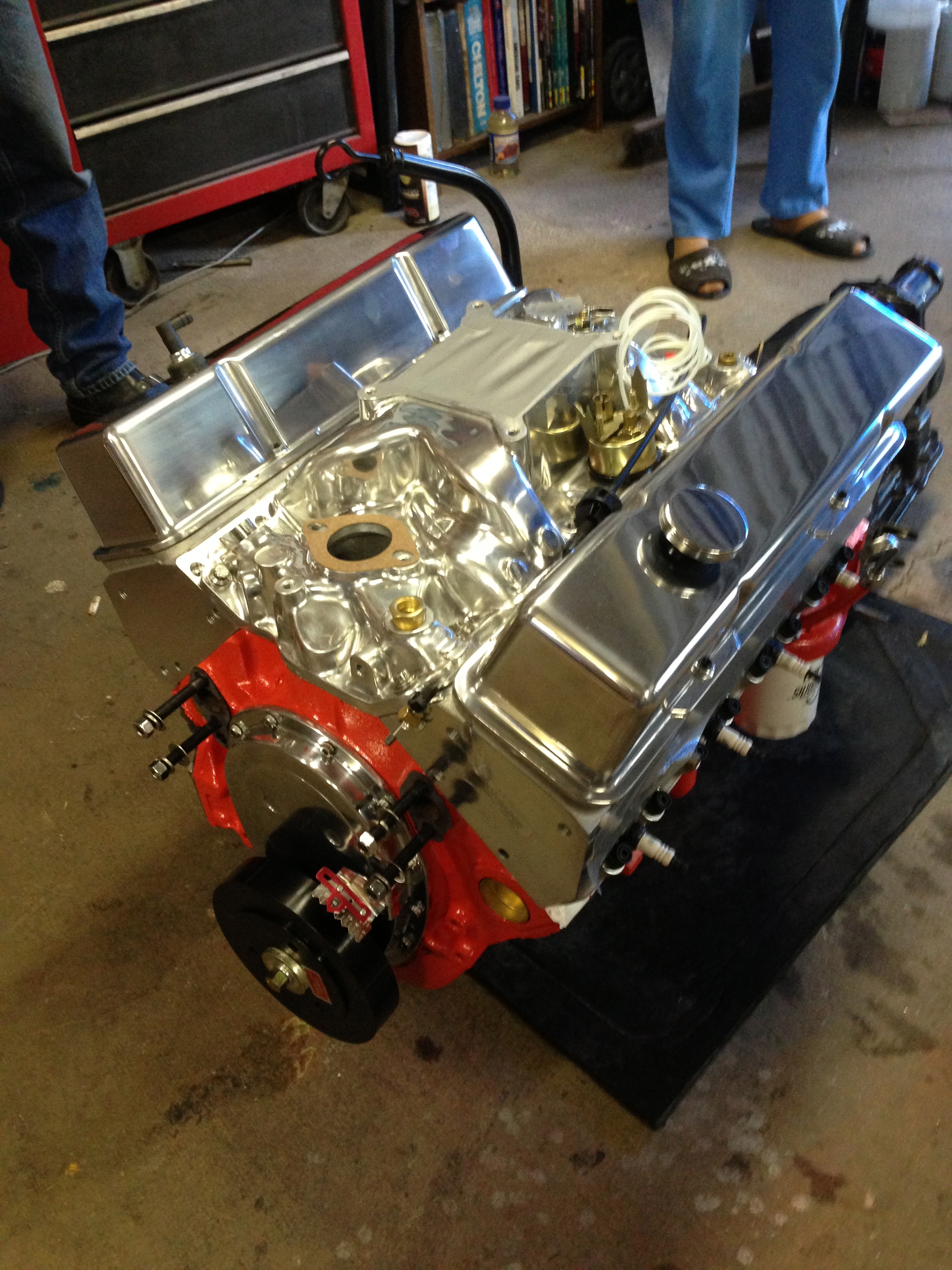
Well, it’s been busy around here.  I spent the last few months finishing out our metal building as my new workshop.  That involved a lot of spray insulation, paint, construction, electrical work, and creative waterproofing.  I now have 10 new outlets on a new 50amp circuit and new breaker box, an insulated workplace and some good organization.  I did all this so that I could move all of my tools from our downstairs garage up to the new workshop to create space for the truck.  When the truck gets back from paint (which will hopefully be very soon) I will park it in the downstairs garage where I can pull the engine, install the new AC components and strip and paint the engine compartment.  The engine is pretty much done!  As soon as the engine compartment stuff is finished, I should be in the home stretch.

It’s been a journey!  Originally, I just wanted to paint the block.  Instead, I ended up starting with a different block, going 60 over (total cap should be around 361), roller rockers, high performance cam and a bunch of performance hard bits.  New intake, covers, heads, yada yada.  I of course have no idea how to do any of this, so I hired a friend’s recommendation to help me out.  He has been awesome, and pretty much made every decision on the engine.  He also talked me into a (purpose built) 700r4 conversion that he swears will not give me any trouble.    It looks AMAZING.  Can’t wait to get started – really praying that the truck gets out of paint very soon.

Categories: Uncategorized Tags:

Let There Be Headlights!

May 24th, 2010 Comments off

Believe it or not, I got my wife to ride in the truck last night!  I lured her with ice cream – but still.  Now that the truck is running (reasonably) well, I’m wanting to take it out more often so an ice cream run seemed like a good start.  After we had finished our Marble Slab goodness, we headed home.  It was probably 15 minutes or so after sunset, so as the heavens went out, I flipped the headlights on.  Now, they have always been a bit dim.  And they had a bad habit of flickering every once in a while that I had chalked up to a loose connection.  Recently I took the connectors apart, cleaned them up, and slapped some bulb grease on them in an attempt to rectify that.  But it turns out I was mistaken – that was not the problem.  Or at least it wasn’t the WHOLE problem, because after the headlights had been on for ten minutes or so, they started flickering again.  And not just a little flicker.  Imagine a signal lamp operator with turrets and you’ll get the idea.

I discovered after some (frantic) experimentation that if I turned the lights out for a minute or so, I could get a few minutes of non-blinking headlight.  But we were ten minutes or so from home – and I’m pretty sure the people around us thought I was trying to tell them to pull over.  So I pulled over and did a bit more experimentation.  I discovered that if I unplugged one of the lights, the other would operate flicker-free.  so we went the rest of the way home as a popeye.

Some research led me to believe that the problem lay in the wiring.  A common upgrade for old C/K trucks is a “Headlight Relay Upgrade”.  The OEM system routes power from the battery, through the fuse box, through the headlight switch in the dash, through many feet of wire, to the driver side light, through several more feet of wire and finally to the passenger side light.  That is a lot of room for resistance.  This resistance can eventually cause the switch to overload, hence the blinking.  It also results in dimmer lights, as they aren’t getting the voltage they really need.  The solution is to take the lights out of the circuit and instead have the power from the switches activate two relays (one for low beams and one for high).  then you can run higher gauge wire directly from the electrical system, through the relays and into the lights.  Much less resistance.  If you Google it you’ll get a ton of pages on it, but my favorite, and the one I used is here. Really helpful info.  I ended up using  Optronics A715 relays – less than four bucks a pop at O’Reilly’s.  I used 10 gauge wire for most of it which was overkill and a bitch to solder, but it was what I had on hand.  At least in the future if I want to add HIDs or something I won’t have to run new wire.

It took about four hours or so, but the result is working headlights.  They do seem brighter too, so bonus.  Another problem taken care of!

The big problems left now are:

  1. Paying someone to replace the oil pan and gasket
  2. Replacing the transmission pan and gasket
  3. Getting the carb adjusted or rebuilt
  4. Replacing the rust tank and lines
  5. Rebuilding the rearend
Categories: Uncategorized Tags:

Engine Work

May 22nd, 2010 Comments off

Lots of fun stuff recently.  I’ll admit – I’ve lost steam a little bit.  Having the bad experience with the rockers and then the bad luck with my Ion really took the wind out of my sails.  And the money out of my wallet.  I figure I have now flushed almost $2500 on those two problems now, only to end up right back where I started.  Cheeses me off a bit.

But that makes progress feel all the better!  I was telling my buddy Greg about all the leaks and whatnot and how the truck wasn’t running as well and he offered to lend a hand.  He has rebuilt several American engines, and is easily one of the most intelligent people I’ve ever met.  Plus he has a kickass Z.

The major symptoms were:

  1. It ran like crap
  2. Coolant was dripping from the bottom of the timing chain cover
  3. It was overheating
  4. It leaks oil and transmission fluid.  A lot.

The oil and tranny fluid would have to wait, but he was pretty sure the coolant was actually from the water pump.  This scared me because getting to the water pump meant taking out the radiator, fan, belts, and various other intimidating looking bits.  But hey – learning experience right?  So I began to prepare.  Greg said he could come over some weekend day and we could get it knocked out.  I decided to get as much of it done as possible before he came over so I had time to paint the bits I was taking off, and to get a good look at everything.

I decided that if I was going to take the radiator out, I might as well put the right size back in (not that I don’t love the “ziptied radiator” look).  So I bought a new radiator in addition to the new water pump and gaskets.  I then started to remove all the components.  I kept a really detailed list of everything I removed, and the order in which I removed it.  For each step I took a baggie and put any small hardware from that step in the baggy and labeled it with a sharpie, making sure to separate unlike sizes and lengths.  I also took the time to strip and repaint the alternator brackets, part of the tranny lines, air cleaner housing, fan and fan clutch and radiator mount.  I also snagged a new battery tray because the old one was pretty much nonexistent.

I also decided that it would be a good time to replace the thermostat housing which has leaked ever since I changed the thermostat last, and also to check the plugs.  Why check the plugs you ask?  Because when I last put in plugs, I didn’t gap them.  Yes, really.  I realized too late that I didn’t have a gauge.  So instead of jaunting down to the parts store I decided “What the heck.” and just didn’t gap them at all.  So yeah – mystery on why it was running poorly was solved.  So I pulled the plugs and gapped them.  I redid the thermostat housing as well and SOMEHOW (I still don’t understand how) I put the thermostat in upside down.  I was very surprised when I took that housing off.  So overheating problem solved!  I used a thin layer of Permatex 2 for the thermostat housing.  The new housing required slightly different length bolts than the old housing, so that meant another trip to the parts store.  It also had a brass plug in a threaded hole where a temp sensor can go (I guess).  I found out much later that you need to REMOVE that plug and seal the threads before you put it in.  Yeah, that was fun.

Anyway, on Saturday Greg came over and we got to work.  We hit some fun snags, like the fact that the PO had decided to use only 3 of the 4 required water pump bolts (wonder why it leaked?)  But eventually we had all the right hardware, and we put a thin layer of Permatex Thermostat Housing and Water Pump sealant on the block, and to one side of the gaskets.  Then stuck the clean side of the gaskets to the sealant on the block, and put on the pump.  I can vouch for that sealant – really impressive stuff.  No leaks!

Put everything back together and filled up the new radiator – runs like a champ now!  Well, ok , it did after a new fuel filter (darn rust!).

Altogether, a freaking great Saturday.

Categories: Uncategorized Tags:

The Clunky ION Is Repaired

March 31st, 2010 Comments off

So yeah.  Took the clunky ION back to the shop since I was now sure after my tests and research that it was the lower control arm bushings.  They are morons, and even after I told them what was wrong they still thought it was something else.  They allowed me to go back to the lift where I showed them with a screwdriver the same thing I did in my earlier video.  They said “Oh we hadn’t made it back that far.”

It’s 12 inches away.  In fact, they would have HAD to have removed the ball joint to replace the strut and it is attached to the stinking control arm.

But don’t worry!  They offered to fix it for free.  Oh no wait! – that would have made SENSE!  No, in reality they wanted me to pay an ADDITIONAL  $300 to fix the bushings.  And they would be replacing them with OEM.  So I said I’d think about it, which really means “I’ll be egging your house later, thanks.”

I ordered the Prothane bushings carried by Never Enough auto – and they are the BOMB and you should totally get some if you have an ION and have this problem.  The instructions are pretty good, though they gloss over some bits I wish they had elaborated on.  essentially the process is to remove the control arm, remove the old bushing (or in my case “Let the old bushing which is no longer attached in any way shape or form to the control arm fall merrily to the floor”), cut out the old sleeve, clean everything, grease up the new bushing, and press it in.

So the parts I thought would be really  hard weren’t.  But some parts I had not even given any thought to were about like trying to do rectal surgery on one’s self.  I just removed the bolts from the control arm to the subframe, the big bolt through the lower bushing, and the ball joint pinch bolt and the whole arm came out pretty easily.  Basically the old lower control arm bushing just fell out.  So I didn’t have to press that out.  And I also didn’t end up doing the front bushings because they didn’t really need it, and also I couldn’t understand how to get the mounting bracket out of the old bushing.  Pressing the new ones in was somewhat fiddly – especially with no actual press (if you are going to do this – pay the money for an actual tool or at least the $50 for a harbor freight arbor press.  )  Also, you really HAVE to install them from the top side of the arm or they will just never go in, because the top side is nice and beveled an the bottom side is sharp.  But it wasn’t really difficult.  No, the hard part was yet to come…

The fun began when I tried to get the arm back in. The clearance for the metal sleeve within the lower control arm bushing is exactly the same width as the opening into which you slide the lower control arm section.  So there is no room for error.  and that would be no problem at all – if you could slide it in directly from the side or end.  but you can’t.  Because the balljoint end of the control arm is hitting the wheel mount.  And short of REMOVING the wheel mount, there isn’t a whole lot you can do about it.  But I wasn’t about to do that, so I went with the “Yam It In” method.  It is a GM certified technique.  It didn’t work.  All it did was cut into the lower side of the bushing.  I finally ended up having to wedge the top portion of the bushing in, and the use the floor jack to apply pressure to the bottom bit of the bushing that was sticking out to kind of compress things a little.  Then it slide on it, but it wasn’t easy.  (on the other side, I figured out you can bend a thin piece of sheetmetal on the top and bottom edges of the opening and grease them up to help it slide in without cutting into the bushing)

I thought my pain was over, but I was wrong.  The lower control arm bushing bolt had to be reinserted.  But the sleeve in the bushing was at an angle to the holes the bolt goes through, so it wouldn’t line up.  If I got in the bolt at the bottom, it just jutted out at an angle – it was nowhere near the top hole.  If I tried to torque things to line the TOP hole up, the bottom hole bit into the bolt threads and got stuck.  So I had to sit there with a screwdriver shifting things around for like an hour (really) before it would finally line up.  The other side was worse for some reason.

But, five hours after I started, it was done.  And now there is NO CLUNK!  So I’m happy.  Tomorrow I’m taking it into to a DIFFERENT shop to get the squeaky coils fixed.  I’ll have them do an alignment while I’m there.

Categories: Uncategorized Tags:

The Floorpan and Rocker Situation

March 26th, 2010 Comments off

So, you may remember that I had the floorpans and rockers done.  Well, I’m going to have to have them redone.  Are they in?  Absolutely.  Are they “daily driver quality or at the very least installed correctly so the rust will not come back”?.  Unfortunately no.  I didn’t think – nor did I WANT – a show quality level job done.  I just wanted it to be presentable, functional and NOT have bits welded over rusty bits.  But no such luck.

I’ve been stewing about this for a while because I really liked the guy – he was a really nice guy.  And he said up front “this will be daily driver level quality”.  And that would have been fine.  But come on – I mean take these things into consideration:

  1. The doors scrape the rockers.  Granted the doors are not in fantastic shape – but they didn’t hit the OLD rockers.  The replacements should be no different.
  2. There is body filler just slapped over rust.  I know this because I have eyeballs and when you scrape off body filler you find old paint and rust underneath.
  3. Welding new panels over old rusted ones.  I mean, I didn’t expect him to sand blast it.  But I did expect him to hit it with a DA sander or something.  Where the panels overlap you can look up inside and see the old rusty panel.
  4. The floor pans are high enough to prohibit the gas pedal from going down more than about a 1/4″.  I fixed this by bending the pedal arm, but what a kludge.
  5. None of the trim fits now.  I would have to cut about an inch off the bottom of the trim to make it fit.  No thanks.

Anyway.  I wasn’t expecting him to stitch butt-weld it or anything.  Just to flange it and spot weld it so stuff lines up right.

I’m now on the prowl for someone to fix it.

Categories: Uncategorized Tags:

Gas Pedal

March 24th, 2010 Comments off

I’m noticing that fixing little annoyances seems WAY more rewarding than fixing huge issues.  On thing that has been bugging the crap out of me is the gas pedal.  It was really… odd.  Not stiff, per-say, but just “unrefined”.  It sort of felt like stepping on a piece of scrap wood that happened to be lying on top of other scrap wood.  Kind of floppy and loose.  And it pretty much had two indexes: “no gas” and “floored”.  Also, it was looking pretty tired.

I the pedal bracket and disconnected the accelerator cable.  After pulling it out, I noticed that a big part of the problem is that the spring on the backside of the pedal was snapped.   Also, when I had the floor pans done (which I will be having RE done – more on that later) the new pan is waaay higher than the old one.  So the pedal was bottoming out.

So I went to O’Reily’s (I love O’Reily’s) and tried to pick up an accelerator cable and some springs, but they didn’t have either in stock.  I was going to just put it off, but then I decided that I just couldn’t wait and went to a different parts store.  They didn’t have the pedal spring, so I just grabbed an assortment of throttle control springs.

I wire wheeled and cleaned all the medal bits and washed the rubber pad, then gave the metal a fresh coat of paint.  I modified one of the large throttle return springs to act as a replacement for the pedal spring.  I had to bend the pedal shaft a bit to give myself more floorpan clearance.  I then installed some new throttle return springs and the new accelerator cable and put everything back together.  And WOW there is a huge difference.  Feels like a normal gas pedal now!

100_1152

Categories: Uncategorized Tags:

Long Story Short…

March 24th, 2010 Comments off

So I took the ION into a local shop to get the “clunk” that it makes when it goes over bumps at slow speed checked out.  All my research pointed to it being caused by a worn lower control arm bushing.

But, not knowing how best to check to see if mine was bad, I took it in.  I told them I thought it was the lower control arm bushing.  they said “No, it is your strut plates.”  Crap.  So I had them change those out and while they were at it I told them to put in new struts.

$800 later, it still clunks.  So I threw it on the jack stands and did some poking around.

I’m no suspension expert – but I’m pretty sure this isn’t supposed to happen…

embedded by Embedded Video

Categories: Uncategorized Tags:

More Thought on Gauges – and SHOCKS!

March 14th, 2010 Comments off

So I really want to go more in depth on the gauge work that I did – because it was a LOT of work, and I really like how it turned out.  So I want to be sure and document it.

The basic issue was that in my original cluster I had a speedo, a fuel gauge, a clock (that didn’t work), a temp (that didn’t work) a voltmeter and an oil pressure (that – you guessed it -didn’t work).  But that isn’t what I WANTED!  And also, they looked old and nasty.  So I thought to myself, “Well, how hard could it be to just modify the gauges from the cluster to replace the non working ones, and to move the fuel gauge to the smaller location?  And while I’m at it migrate a tach into the slot where the fuel gauge USED to be?  And design new faces for all the gauges too!”.  The answer is very very very hard.

I created new gauge faces by taking LOTS of measurements, and plugging everything into Illustrator and designing a whole new matching set of gauge faces.  I printed them out on photo paper and used a craft knife to carefully cut them out.   When each gauge face was prepped properly, I used double sided adhesive to stick them in place.  As I’ve mentioned before I will probably have to go back and replace them with vinyl printouts because the paper curls in high humidity.

I first had to chop the cluster housing all to bits.  Then cut up the original gauges.  First I cut out the old parts to the clock and threw them out.  Then I took the fuel gauge internals and cut them off the large face they were on, and moved them behind the old clock face and epoxied them in place.  That took about 5 hours because it involved a lot of tiny-part-fabrication and lining things up over and over and over.  On top of that, I had to create and entirely new needle for the fuel gague – the old one was way too big, and the needle from the old clock wasn’t the right size or shape at all.  So I made a new needle out of lexan and painted it to match (it came out really well too – you can’t even tell)  I was able to test the fuel gauge out and position the new needle correctly by using a 9volt battery and a 90 ohm resistor.  The three poles on the back of the fuel gauge are a positive, a negative and a signal line.  If you place a 90 ohm resistor in the right place, and then test it with the circuit completely open, you are basically simulating the sender unit. So you can go “Ok – it should read FULL now” and then position the needle accordingly.

I then moved on to the oil and temp gauges.  I ripped them out of a sunpro gauge cluster.  I cut out the old internals for the original gauges and mounted the sunpro internals behind the faces taking care to line everything up right.  This was a royal pain in the arse, but when it was all said and done everything lined up well.  I placed in their new faces and tested them out and positioned the needles.  To calibrate the oil pressure gauge I created a small pressure chamber out of a section of PVC pipe with a schrader valve and a port to screw in the oil pressure lead.  I also added an additional PSI gauge into the chamber.  I then used a hand pump to pump the chamber to given pressures (20, 40 , 60, 80) and made sure the needle on the new frankengauge matched the ones on the hand pump and the additional pressure meter.  Amazingly, I got it on the first try.  They all pretty much matched up.  To calibrate the temp gauge, I brought some water on the stove up to various temperatures and put in the temp probe.  Needle placement was pretty easy!

Then I cut up the sunpro tach and mounted it in behind the old fuel faceplate.  That required a looot of plastic surgery, but it turned out well.

I wanted new lighting too, so I created a network of red LEDs on the interior of the gauge shroud.  It took a lot of trial and error to get everything to fit back together with the added bulk.  I then did some major wiring to the back circuit to get everyone routed to their new homes.  I then installed the new cluster and routed the new temp line and oil line to the engine.

ALMOST everything worked.  The tach didn’t work at first because the ground had been cut by the guy who did the floor pans.  After hooking it back up though, it was fine.  The LEDs didn’t work because the sot I wired them into had some sort of issue – so I had to rewire them to a different bulb feed.  The fuel gauge jumped around because it had a short.  But ofter sorting those things out, everything seems rockin now!  Plus the lights look really nice.

So yeah.  Lot of work but really really worth it.

The other thing I’ve gotten done recently is new shock absorbers.  The truck was really bouncy.  So much so that it felt unsafe.  So my buddy James came over and we tackled putting in a new set of shock absorbers.  Took about 6 hours for all four – but most of that was trips back to O’Reilly’s for sockets and wrenches.  I ended up having to buy a new socket and 2 new wrenches AND a new set of extensions.  I swear every single bolt had a different sized head.  I put Monroes in the front, and would have put them in the back too – but O’Reilly’s only had the one set in stock.  So I had to go with the cheapos in the rear.  I may change those out again before too much longer while all the hardware is still fresh.

Lemme tell you – new shock absorbers make all the difference in the world.  The ride is totally different.  I was shocked (hah!).  Much easier handling – and it feels more real somehow.  Much more like a vehicle and less like a deathwagon.  I can seriously see after I get the interior done and finishing out the suspension and steering gear box wanting to drive it every day.  Ok, and replacing the windshield.  And mirrors.  And weatherstripping….

Categories: Uncategorized Tags:

Merry Christmas!

December 26th, 2009 Comments off

Wow!  I made out like a BANDIT this Christmas.  I got awesome handmade socks from the missus, AND lots of truck parts.

Looks like my wish list paid off!  Many thanks to all those who participated!  I scored a set of cab-side weather striping for my doors, a set of chrome repro mirrors (Love the look of those – can’t wait to get them on!), all 4 wheel arch trims AND new vent window knobs!  I’m stoked.

I did however also dent the bimmer in a miscalculated attempt to get her out of some mud.  But it wasn’t TOO bad, and I’m taking it to the wife’s BMW guys asap.  I am of course very very upset about it.  But hopefully it will be right as rain before too much longer.

Here is a pic of the swag! :

christmas

Categories: Uncategorized Tags: